Making A Police Car For Independent Films
/
This all started about two years ago when I decided to try and make one of my film projects a full-length feature. But one of the biggest hurdles was close to the end of the film, the police arrive and arrest the main character (can't tell you why, sorry, you'll just have to catch the movie at a film festival). I incidentally ran across a guy at in our church parking lot who was high up in the ranks of an agency here in Arizona. I had a meeting with him down at his office to discuss what I was planning on doing. He said that he was fine with it, but the ones above him would most likely have issues with using their cars and emblems. They would be a lot of scrutiny of what I could use and what they would keep from me. To avoid any real politics, I decided to make a police car.
The Car
There are usually old police cars that you can buy on Criagslist. Rather cheaply too. Sometimes they still have the old police paint job with the black & white. Sometimes they have the push bars on the front bumper and the spot lights. If you're really lucky, they will still have the siren, wigwags (headlight flashers) and even the computer stand that you can toss any laptop into. I have found these ranging from $1000 to $4000 with various years & colors. At this time, for the movie I'm planning to make, I know a guy who owns one so I think we will be borrowing his. I figured I would mention that as it was part of the original plan. With all that, I have yet to see one on craigslist that comes with the lightbar on top. So, my challenge.
The Lightbar
Obviously, as I still only have a shoestring as the budget for this movie of mine, I do not have $500+ to drop on a lightbar that would only have one purpose, let alone if I would be able to buy one anyway. I figured that I've played around with 555 timers before; maybe I could make a circuit that would flash lights in a way that could be convincing for the [literally] 4 or 5 seconds the cars would be on the screen.
The Circuit
A few years back, I had a small caprice model that I was planning on building and turning into a model police car for fun. Never did get that finished. Not sure what I did with that now that I'm thinking about it. I went to Radio Shack and got some small red and blue LEDs, a handful of resistors & capacitors and a breadboard and started plugging things together.
My dad had taught me a lot about the things you could do with 555 timers and I remember doing a lot of experimenting with them. But my favorite thing I learned was the astable multivibrator (stop snickering back there!). This is a easy circuit to set up the basically goes on, off, on, off. There is more in depth information here if you are interested:
http://www.electronics-tutorials.ws/waveforms/555_oscillator.html
I knew that you can toss a few LEDs on that circuit and all will work well, but if you exceed the output of the 555 timer, you will cook your 555 timer. I have cooked many and they stink when they cook! I went to get some help on a forum and throughout the two years, I have had a couple people help me out. I've had to put the project down at months at a time with the hurdles of life as they have come up, but was always offered some friendly advice along the way. If you are interested in more of the technical sides of this and see that you can be precise in all things/math involved, or be like me and fudge it here and there, read all the pages here:
http://www.physicsforums.com/showthread.php?t=624835
One of the things I posted was a crude animation of what I was planning to do:
As you can see, my original plans were before I encountered how much LEDs were going to cost. I also had confused the people on the forum with how my mind would change fluidly as I went about this project. Originally each bank was to have 20 LEDs, and then 10 more banks of 20 yellow LEDs to work like an arrow, or a construction sign/truck/sweeper/what-have-you. I found this place in Hong Kong that offers cheap LEDs and free shipping:
http://ledshoppe.com/led10mm.htm
When I did the math, I found that it would be $60 for the yellow, $24 for the blue, and $8 for the red. $92 bucks wasn't too bad when a real one is $500, but I wanted to save as much as I could. I wound up getting 20 yellow, 50 red, and 40 blue for $30 - that's more my speed. I figured that if it wasn't bright enough, I could cross that bridge when I got there.
As I mentioned before, the 555 timer will go on and off. I wanted more of a blinking when it was on so where I had left off with the model, I picked up here. I figured I could have one 555 timer turning on and off another 555 timer which is set at a much faster rate. So essentially it would go on,off,on,off,on,off --pause-- on,off,on,off,on,off --pause--. Instead of using two 555 timers, you can get a 556 timer which is essentially 2-in-1. I think that makes sense, but re-reading it, I think a small video would explain better:
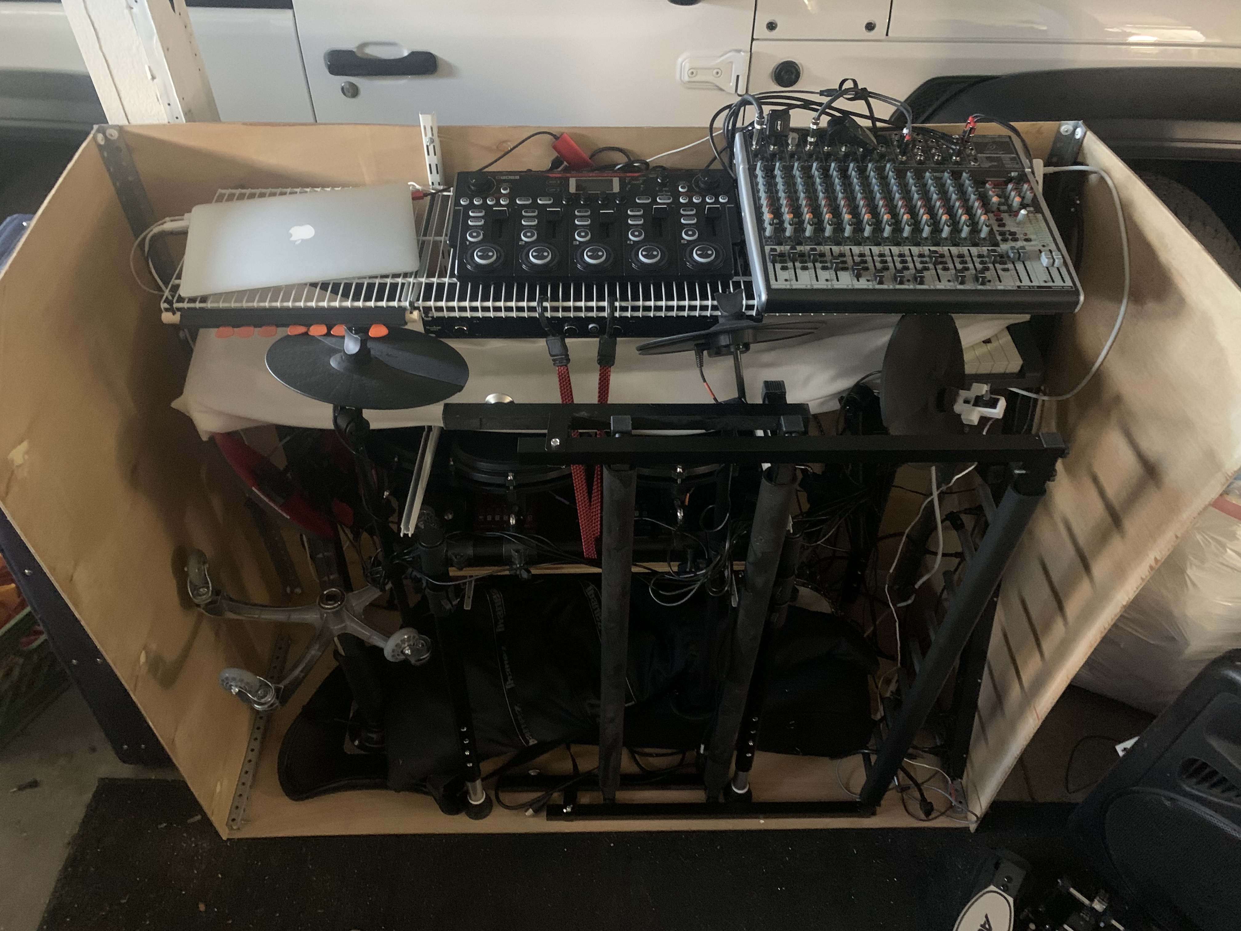
Meanwhile, me and another cat were talking about how to put the circuits together. We went back and forth about the precision of the values of things that I could not get my head around. I wound up building a test circuit on my breadboard and some blue LEDs. I put together two segments, one red and one blue. My first step was to see if they would be bright enough at night for the camera to pickup without doing anything extreme in the ways of ISO being super high - just a larger aperture. It seemed to work out okay so then I was afraid of burning parts out. With a giggle, I was able to test a segment of blue for a few hours:
I am not a good solderer
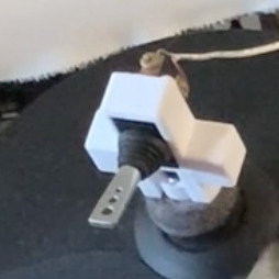
A big downfall of mine in the project is that I cannot solder nice and neat. I did a little research about printing out circuit boards so I could just solder parts to it, but never got to a point where I could get a quote. Mostly because I never made a schematic because I don't know how. But when I got around to it, I painstakingly soldered together the small one in the video, and the two in this picture:
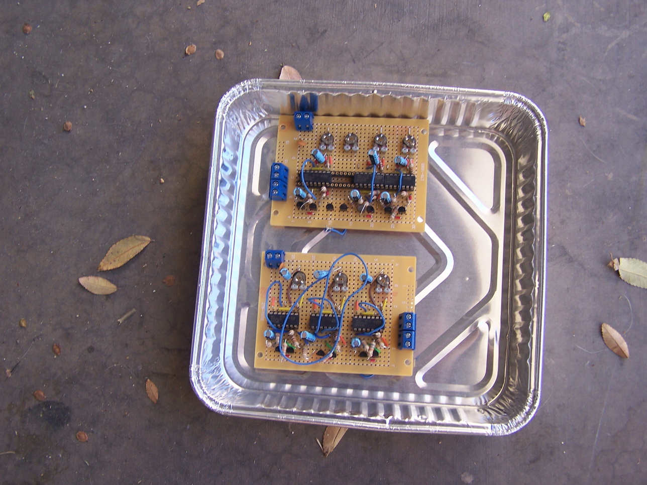
As you can maybe see, my intentions were good. I got all of my parts and put them altogether on the board. Didn't realize that 4 556 chips would not fit correctly next to each other without grinding away some of the packaging of the chip. I had made 6 on each of these boards. For some reason that I never found out; when I put these board together I had 6 working circuits with nice handy outputs on those blue blocks. I started testing with them and two of the circuits just continuously blinked. I compromised and figured that's okay, I'll just keep those blinking. But one segment stopped working. I fidgeted with it until it did work again just to find that another one stopped working. I had originally planned on making individual circuits so if one stopped working I could swap them out. But at this rate; I'll never get it working. I decided to back pedal. I started looking for a transistor that could drive 40 LEDs at once. I found a website that simply showed me how I can take a working circuit on my breadboard and drive half the LEDs:
http://www.555-timer-circuits.com/increasing-output-current.html
TIP31 Transistor
I went to Radio Shack (again) and got a couple transistors. In my haste, I will admit that I cooked two of the 556's you see in the pan above. So now like 2 still work. Errrr. I had bought extra in the way of parts so I just built two more circuits with 556 timers that I will go through with you now:
I have yet to put a schematic together for you. I have a few drawn out but they are really messy. I use 1 100K ohm adjustable resistor, all the circuit's resistors are 1K, 2 10mu capacitors, the 556 and then whatever LEDs you use. Feel free to comment if you need more info before I get to it, send me a message and I'll get it for you.
Printed Circuit Boards
In the future, and also for this same project, I'm trying to use this freeware program to design a printed circuit board for making multiples of this little circuit. I'm hoping I can think ahead and retro-fit it for larger transistors or even full sized relays so that I can connect it to head and tail lights.
Update 3/21/2015 :: Cost
Due to a youtube comment, I decided to add in an approximate cost of the parts I used to make the lightbar.
| A couple notes about these figures... All of the hardware I got at Home Depot or Ace Hardware here in town. These prices are pretty normal for locally, but I found while looking up these prices, I noticed that you can get all of the hardware for about 1/2 the cost - sans the wood. You could probably get it cheaper, but then shipping would cost twice the amount of the wood. In case you wonder, yes, blue LEDs are twice as expensive as the other colors. Why? I guess they use blue Kryptonite. Who knows A lot of the small electronic parts I had laying around here and there, wire I either used old breadboard hookup wire and harvested wire from broken appliances, and good will. You can get tons of speaker wire for pennies on the dollar, especially on half-price Saturdays. That being said, I guestimated $35 because I figure if I went to an electronics place like Circuit Specialists in Mesa. They have tons of cheap parts. I think I spent about $35 there and got a lot extra. Expected heartache and blowing up parts - which I most certainly did ;) | ||||||||||||||||||||||||||||||||||||||||||||||||||||||||||||
Comments
Categories
- Stupid Stories 65
- On My Commute 31
- Computer Programming 21
- Italian Dual Citizenship 11
- Food 9
- Black Lives Do Matter 8
- The Beast 6
- Not So Stupid Stories 6
- Quick Projects 5
- Playing Out 5
- Movies I've Made 4
- Old Man Rants 3
- Scams 3
- The Robot Sbot 2
- Other's Music 2
- Film Projects 2
- Programming Tutorials 2
- Making Movies 2
- Rental Car Reviews 1
- My Original Music 1
- 3D Printing 1
- Ryvid Anthem 1